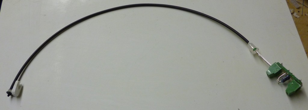
I have assembled the N scale signals for the Two Siding Oval layout.
This assembly consists of a BLMA Models #1000 non-operating N Signal Head (mounted on a piece of styrene), a length of fiber optic cable (Mouser #630-HFBR-RNS001Z), a two color (red/green) LED (Mouser # 696-SSLLX5099GIWCA), and a small circuit board containing series dropping resistors. The Two Siding Oval layout will have four of these assemblies, one at each of the stop and wait locations.
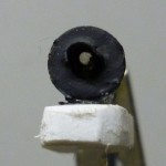
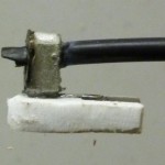
The non-operating N Signal Head is an easy to assemble etched brass kit. I drilled a 1mm hole in the back to allow a for a fiber optic cable. The other end of the length of cable (about 1/4 of the meter long cable assembly) is mounted in a 1mm hole drilled about 1/8" into the LED.The LED is then connected to the resistor board. I painted a green dot next to the green lead of the LED for ease in orienting the LED when connecting it to the resistor board.
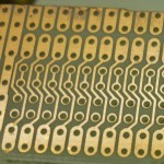
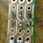
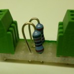
The resistor board is made from a piece of the connector section cut from a ST6U strip-board (Mouser #854-ST6U) with a Dremel tool using a cutoff wheel, two 510 Ohm 1/4 watt resistors (Mouser #660-MF1/4DC5100F), and two 3 position 2.54mm (.1") pitch screw terminals (Mouser #571-2828343). I painted one edge of the resistor board green to ease in orienting the LED when connecting it to the resistor board, although the resistor board is symmetrical. The resistor board provides two series dropping resistors (for the two cathodes) and a jumper for the center connection (for the common anode). The center (common anode) connection goes to the plus side of the 12DC volt supply and the two other connections will go to a relay that will connect one or the other (red or green) to the minus side of the 12 volt supply.

