Additional Places
Category: What’s on the bench Posts about what is current on Uncle Robbie’s Workbench. That is, what I am working on at present.
Sir Top'm Hat gets a new hat and starts
Model RR signals with an
Arduino, Programming the Arduino
The code to download to the Arduino is in available for download as SignalDriverMax72xx_Ardunio.zip. It uses the LedControl library, so the code starts by including the header file: #include <LedControl.h> Then since it is using scanf() and various string function, it includes stdio.h and string.h: #include <stdio.h> #include <string.h> Then…
Model RR signals with an
Arduino, Assembling signal targets
Model RR signals with an
Arduino, Signal Driver board cables
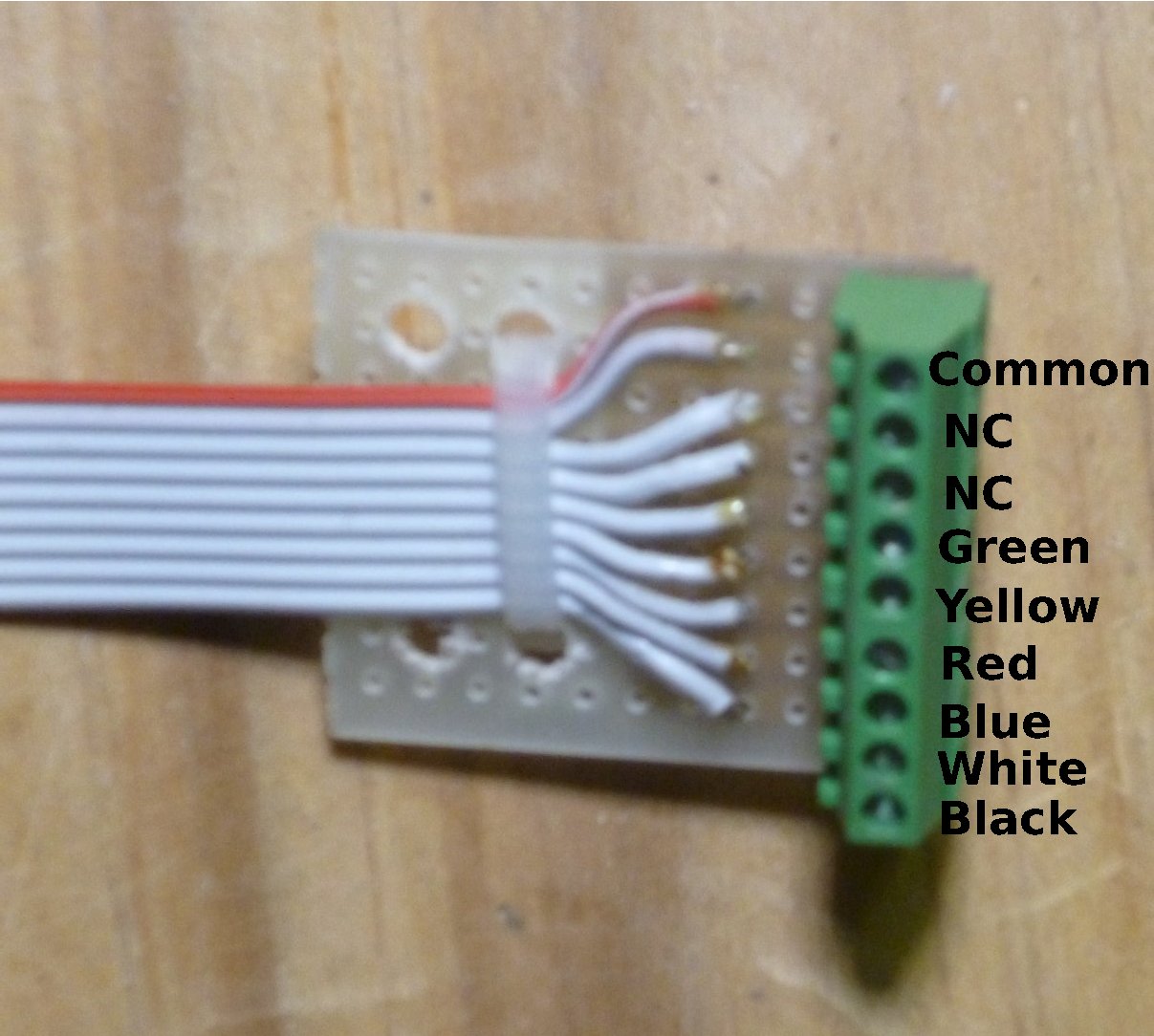
Nine conductor ribbon cables (DigiKey part number MC09G-25-ND) is used to connect between the Signal Driver Board and the signals. One end gets a 9-pin header plug and the other end gets a small circuit board with small screw terminals. The actual LEDs in the signals are connected to wire…
Model RR signals with an
Arduino, Connecting the Signal Driver Board
The Signal Driver board is connected with a home made connector cable. The cable is a six conductor ribbon cable (DigiKey part number MC06G-25-ND). One end of the cable is attached to a 6-pin .1 inch (2.54mm) IDC header plug and the other end connected to a "plug" made from…
Model RR signals with an
Arduino, Signal Driver board
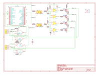
The Signal Driver board is assembled on a piece of "strip board", specifically a 3.5 inch by 2.5 inch piece cut from a BusBoard Prototype Systems BPS-MAR-ST6U-001 (included in the Mouser project). After cutting this piece from the board some of the copper foil needs to be carefully removed. This…
Model RR signals with an
Arduino, Introduction

I will be building an interlocking plant module with 5 two-headed signals. To drive all of these signals I will be using an Arduino and a Max72XX Led driver (see http://playground.arduino.cc/Main/MAX72XXHardware for more information about general uses for the Arduino and the Max72XX chips). This article describes the hardware involved,…
N Scale signals
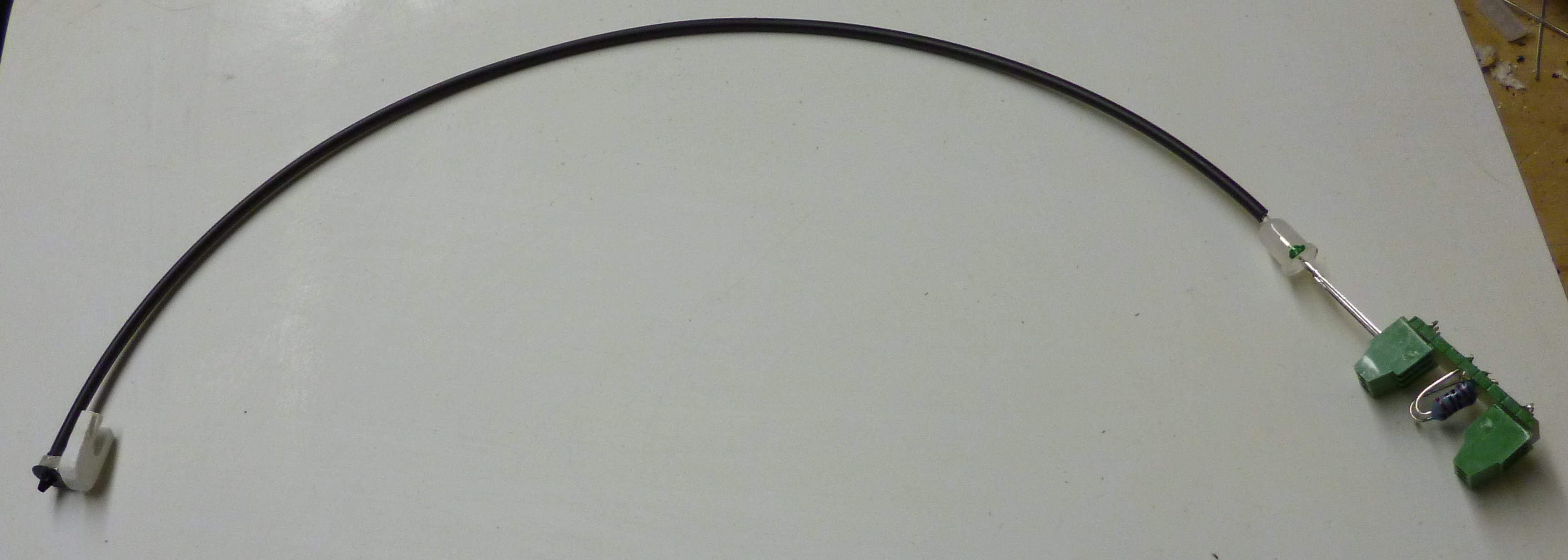
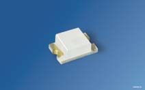
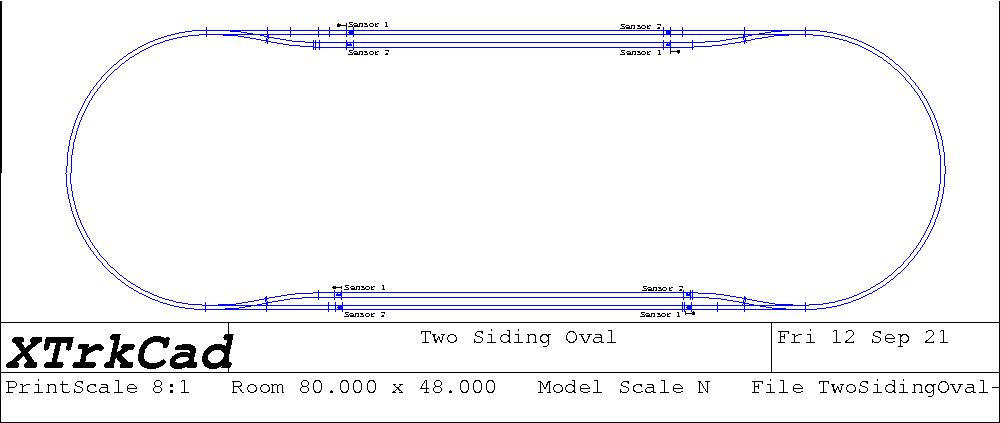
I have assembled the N scale signals for the Two Siding Oval layout. This assembly consists of a BLMA Models #1000 non-operating N Signal Head (mounted on a piece of styrene), a length of fiber optic cable (Mouser #630-HFBR-RNS001Z), a two color (red/green) LED (Mouser # 696-SSLLX5099GIWCA), and a small…
Coming Soon
Posts about what is current on Uncle Robbie’s Workbench. That is, what I am working on at present.
Sir Top'm Hat gets a new hat and starts
Model RR signals with an
Arduino, Programming the Arduino

The code to download to the Arduino is in available for download as SignalDriverMax72xx_Ardunio.zip. It uses the LedControl library, so the code starts by including the header file: #include <LedControl.h> Then since it is using scanf() and various string function, it includes stdio.h and string.h: #include <stdio.h> #include <string.h> Then…
Model RR signals with an
Arduino, Assembling signal targets
Model RR signals with an
Arduino, Signal Driver board cables
Nine conductor ribbon cables (DigiKey part number MC09G-25-ND) is used to connect between the Signal Driver Board and the signals. One end gets a 9-pin header plug and the other end gets a small circuit board with small screw terminals. The actual LEDs in the signals are connected to wire…
Model RR signals with an
Arduino, Connecting the Signal Driver Board
The Signal Driver board is connected with a home made connector cable. The cable is a six conductor ribbon cable (DigiKey part number MC06G-25-ND). One end of the cable is attached to a 6-pin .1 inch (2.54mm) IDC header plug and the other end connected to a "plug" made from…
Model RR signals with an
Arduino, Signal Driver board
The Signal Driver board is assembled on a piece of "strip board", specifically a 3.5 inch by 2.5 inch piece cut from a BusBoard Prototype Systems BPS-MAR-ST6U-001 (included in the Mouser project). After cutting this piece from the board some of the copper foil needs to be carefully removed. This…
Model RR signals with an
Arduino, Introduction

I will be building an interlocking plant module with 5 two-headed signals. To drive all of these signals I will be using an Arduino and a Max72XX Led driver (see http://playground.arduino.cc/Main/MAX72XXHardware for more information about general uses for the Arduino and the Max72XX chips). This article describes the hardware involved,…
N Scale signals

I have assembled the N scale signals for the Two Siding Oval layout. This assembly consists of a BLMA Models #1000 non-operating N Signal Head (mounted on a piece of styrene), a length of fiber optic cable (Mouser #630-HFBR-RNS001Z), a two color (red/green) LED (Mouser # 696-SSLLX5099GIWCA), and a small…

